

Como um punção de freio de pressão para pescoço de ganso resolve a interferência de ferramentas em curvas em formato de U
Por autor: Mark Hanks
Press Brake Gooseneck Punches are important part of press brake tooling solutions applied to eliminate tooling interference during deep U-shaped bending. Diferente dos socos retos padrão, a gooseneck punch provides additional clearance for long return flanges, preventing manufacturers bend complex sheet metal parts from collision between the workpiece and press brake parts.
This article demonstrates the functionality of a Press Brake Gooseneck Punch and the solving of the interference problem in the creation of U-shaped sections with the use of a case study for the components of a safety cabinet.
1. Por que as ferramentas normais de freio de pressão causam interferência de dobra em peças em formato de U
The simplified models of the inner liner and outer shell of the safety cabinet are shown in Figures 1 and 2.
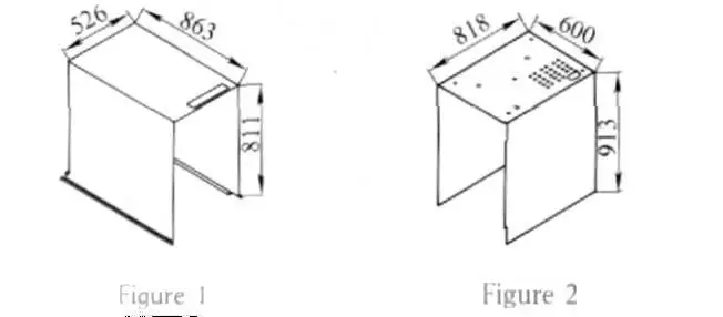
The 3 mm cold rolled steel plate components are formed using a press brake. When the bending action for the inner liner was simulated, an interference issue was detected with the side wall of the inner liner and the front wall of the press brake.
The workpiece and press brake side wall length ratios were determined to be approximately 1.54 and 1.52, respectively. These are both greater than the standard forming range of 1:1 for symmetrical tooling configurations.
Due to the long side walls, a U-shaped section with a length-to-width ratio of near 1 (or above) formed using standard press brake tooling may result in collisions during the folding operation. As shown in Figure 3, the limited space between the workpiece and machine structure can prevent smooth bending without tooling modification.
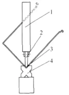
Figura 3: Press-brake-gooseneck-punch-interference-solution.jpg
- Bending Machine 2. Bending Die (Upper) 3. Workpiece 4. Bending Die (Lower)
| Parâmetro | Valor |
| Material | Aço laminado a frio de 3mm |
| Length-to-width ratio (liner) | ~1,54 |
| Length-to-width ratio (shell) | ~1,52 |
| Faixa recomendada para ferramentas padrão | Approximately ≤1:1 |
Tabela 1
2. Por que os socos gooseneck melhoram a situação da folga dos freios de pressão
We examined the tooling for the press brake. The press brake's front panel has a stationary complex large structure that is about 80 mm thick. During operation, this front panel does not move. The worktable of a press brake moves down along with the lower die during bending. Portanto, it is unreasonable and nearly impossible to consider modifying the press brake for the part.
With press brake tooling, proper design enhancements can produce U-shaped part bending results. This requires less effort and does not modify the press brake structure.
A standard press brake die is a left-right symmetrical die with a 45° angle as illustrated in Figure 4. The die movement is in the diagonal line of a square. Using this design, the maximum length to width ratio of a U-shaped part that can be formed is 1:1. Once this ratio is surpassed, one side of the part will hit the press brake and the bending operation cannot be completed.
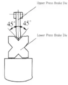
Figura 4
3.Standard Punch vs Gooseneck Punch: Principais Diferenças
When press brake operators select suitable press brake tooling solution, it is important to understand the difference between conventional symmetrical punches and gooseneck punches. Standard punches are suitable for general sheet metal bending applications, but their symmetrical structure generates very few space when forming deep U-shaped parts with long return flanges.
A gooseneck punch uses a special design to create enough working space, allowing previously formed areas to pass through the bending area without interference.
Tabela 3: Standard-vs-Gooseneck-Punch-Comparison-Table.jpg
| Característica | Ferramentas Simétricas Padrão | Ferramentas Não-Simétricas / Pescoço de Ganso |
| Estrutura | Simétrico | Assimétrico |
| Capacidade de formação | Formas de U | Mais flexibilidade de espaço livre |
| Método de alinhamento | Pontas de toque | Com base na liberação |
| Adequação | Formas simples | Formas complexas com seções profundas ou estreitas |
| Complexidade de modificação | Baixa adaptabilidade | Mais adaptável |
4. Solução: Press Brake Tooling Interference Solution for U-Shaped Parts
This special U-shaped part bending tooling provides additional clearance compared with conventional press brake tooling.
Based on the process evaluation, the interference was mainly caused by the excessive length-to-width ratio of the U-shaped component, which exceeded the capability of standard symmetrical tooling.
To solve this problem, a non-symmetrical gooseneck tooling design was developed as an alternative to conventional left-right symmetrical tooling.
The design concept was based on a planar analysis of the U-shaped part (Figura 5). Point B now denotes the location of point A after being moved 40mm. This is approximately half of the 80mm thickness of the press brake panel. From point B to point C, a line was drawn along a diagonal, splitting the forming angle into 30° and 60° sections.
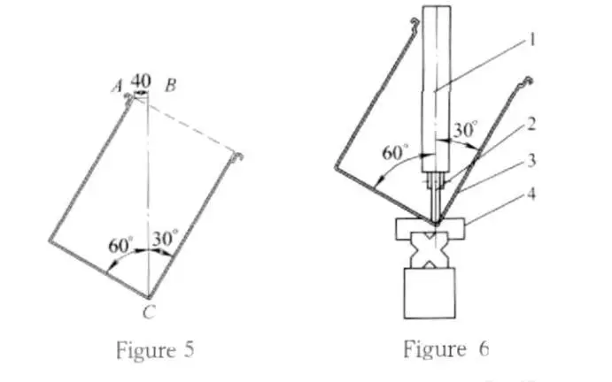
- Bending Machine 2. Bending Die (Upper) 3. Workpiece 4. Bending Die (Lower)
Given these geometrical constraints, the manufacturing of the upper punch and the lower die was done as shown in Figura 6. The modified tooling provides more forming capability of the press brake, as it allows more clearance on the longer side of the U-shaped part.
| Componente | Ângulo | Propósito |
| Parte esquerda | 30° | Dá espaço para a parede lateral estendida |
| Parte direita | 60° | Garante a estabilidade da seção formada |
| Distância de deslocamento | 40mm | Baseado na metade da espessura do painel |
Tabela 2
5. Métodos de Modificação de Punção Pescoço de Ganso para Freios de Pressão CNC
Two modification approaches were developed depending on the type of press brake being used.
Approach 1: Conventional Press Brake Modification
For conventional press brakes, the existing tooling structure is used as the reference base. The original lower die remains installed, while a newly manufactured non-symmetrical lower die is mounted onto it. The upper punch is replaced directly (Figura 7).
This approach provides:
•Lower tooling manufacturing cost;
•Shorter preparation time;
•Simple operation and maintenance.
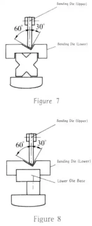
Approach 2: CNC Press Brake Modification
Para Freios de pressão CNC, an adjustable lower die holder is added between the tooling and machine base. The upper punch is replaced with the customized gooseneck punch (Figura 8).
This solution improves flexibility when producing different U-shaped parts with varying dimensions.
Considerações sobre Ajuste de Ferramentas
Adjustment methods for non-symmetrical tooling differ from conventional symmetrical tooling.
For standard tooling, alignment is usually performed by matching the upper and lower tool tips according to material thickness. For asymmetric and gooseneck tooling, tip-to-tip alignment is not advised.
As an alternative, adjustment should be made according to the clearance of the upper and lower tooling:
1.Balance the clearances left and right;
2.Set the clearance to the thickness of the material;
3.Check the tool alignment before starting production.
This method improves forming precision while using the current press brake tools and equipment.
Como selecionar o punção de pescoço de ganso certo para o seu freio de pressão
When choosing a gooseneck punch, manufacturers look at the tensile strength, material thickness and length of the bend as well as the tonnage of the press brake to determine the appropriate tooling.
With every press brake tool, there is a defined limit for the load that is exerted during bending. This is often provided in kilonewtons per meter (kN/m). For standard tooling, this load capacity is between 200 kN/m and 1,000 kN/m. For larger press brakes, with larger tonnage bending applications, special tooling is made of a high strength material.
Some other design considerations include the following:
•Flange heights: This must accommodate the height of the formed flange.
•U-channel depths: This also may require a larger throat or gooseneck.
•Bending clearances: Must accommodate the bending punch, A peça de trabalho, and the previously formed flange.
•Punch design: The design must define the neck and incorporate the bend angle, raio de curvatura, and the height of the bend.
•Tooling design: The punch must define the press brake's clamping system, the die, and the bending operation.
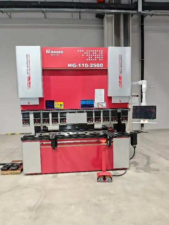
For customers who are unsure which gooseneck punch is appropriate for their application, please contact JS RAGOS. The team provides support for selection, Projeto, and customization of tools to mitigate interference problems in advanced applications involving the bending of sheet metal, given the information for the workpiece drawings and specifications, as well as, O material, Espessura da folha, length of bend, and the requirements for bending and forming.
Conclusão
The use of a custom designed Press Brake Gooseneck Punch, along with asymmetric tooling, eliminates the problem of U-shaped part bending interferences.
This method expands the forming potential of standard press brakes, and does so without requiring any physical changes to the press brake machine. In real-world production settings, it has the added benefits of a lower cost of tooling, a quicker production set up, and ultimately a simpler production process.
For varying U-shaped part designs, the angles of the punches and dies can be altered to fit the clearances necessary. Gooseneck tooling in this respect, is useful for sheet metal applications with long and narrow channels, and long return flanges.
Tabela 4: Gooseneck-Punch-selection-Guide-U-Shaped-Parts.jpg
| Característica da Parte | Tipo de Ferramenta Recomendado |
| Length-to-width ratio ≤ 1:1 | Ferramentas simétricas padrão |
| Length-to-width ratio > 1:1 | Ferramentas não simétricas / pescoço de ganso |
| Flanges de retorno profundas | Soco de pescoço de ganso limpo |
| Largura estreita do canal em U | Ferramentas de gooneck de ponta estreita |
| Formas flexíveis de peças | Com ferramentas ajustáveis |
With years of experience in manufacturing and assembling of sheet metal processing equipment, JS RAGOS offers precision engineering, coupled with automation, and worldwide service support. From press brakes to tools and even robotic bending systems, our solutions offer you optimized and dependable production.
Perguntas frequentes
Q1. Are Gooseneck Punches compatible with CNC press brakes?
Definitely. Gooseneck Punches can be adapted to CNC press brakes with custom tooling.
Q2. What is the advantage of a Gooseneck Punch for U-shaped parts?
Using a Gooseneck Punch avoids tooling problems when bending deep U-shaped parts with long return flanges.
Q3. How does a Gooseneck Punch avoid collisions?
Because of its offset body, the design gives extra space to allow the formed flange to pass through.
Q4. Will a Gooseneck Punch enhance the capability of a press brake?
Definitely, a Gooseneck Punch enables the forming of parts outside the standard limits.
Q5. What parts are suited to a Press Brake Gooseneck Punch?
A Gooseneck Punch is best for deep channels, U-shaped parts, and parts with long flanges.
Q6: Can gooseneck punch be used for deep flange bending?
Sim. A gooseneck punch for deep flange bending can provide extra spaces for flanges and prevent collision in the bending process.
Q7. What is the difference between a standard punch and a gooseneck punch?
Standard punches are suitable for normal bending applications, while gooseneck punches can creates extra space for deep channels and long flanges bending.
Q8. Can a gooseneck punch prevent press brake collision?
Sim. Gooseneck punch can reduce interference between the formed flange, and press brake parts. But gooseneck punches are not universal for all kinds of press brake collision.
Q9. How should I choose a gooseneck punch for my press brake?
Tools selection depends on flange height, Espessura do material, bending radius, tooling height, and required spaces, etc. If you have any doubts with current production, feel free to contact us